Pipe bending reference
Just before the final delivery, our merchandise are stringently checked by a team of quality analyzers on varied parameters, which guarantee their flawlessness and durability. In addition, clients can avail these goods from us at competitive rates.
Standards
ASTM
- ASME/ANSI B16.49 Factory-Made Wrought Steel Buttwelding Induction Bends for Transportation and Distribution Systems
- ASTM A403 Standard Specification for Wrought Austenitic Stainless Steel Piping Fittings
- ISO 2851 tainless steel bends and tees for the food
JIS
- JIS B2311 Universal steel butt-welding pipe fittings
- JIS B2312 Steel butt-welding pipe fittings
- JIS B2313 Steel plate butt-welding pipe fittings
- JIS B 2321:1995Aluminium and aluminium alloy butt-welding pipe fittings
EURO
- DIN 3867 Non-soldering compression couplings - Pressure bush for butt joints
- DIN 2609 Steel butt-welding pipe fittings; technical delivery conditions
- BS 1640 Specification for steel butt-welding pipe fittings for the petroleum industry
- BS 1965 Butt welding pipe fittings for pressure purpose
- STPG38
Recommended pipe bending
Materials
They are manufactured utilizing higher grade raw material, advanced machines and technologies.
- Abrasion resistant: Cearmic lined, Ceramic tile, Bi-metal clad pipe bending, Rare earth alloy wear-resistant pipe bending
- Carbon steel:
- SA234 WPB, SA234 WPC,SA42 WPL6, SA42 WPL3
- WP1. MSS-SP75, WPHY,WPHY 46,WPHY 52
- WPHY 56,WPHY 60,WPHY 65, WPHY 70
- DIN 1629 St37, RST37.2 St52, STPG38
- Stainless:
- ASTM/ASME SA403 304,304L ,316, 316L, WP304L, 3 WP316 WP347 (H) ,WP317 (L),WP321.
- DIN 1.4301, 1.4306, 1.4401, 1.4571
- JIS SUS304,SUS304, SUS304L, SUS316, SUS316
- Alloy:
- ASTM/ASME SA234 WP12, WP11,WP22, WP5, WP9, WP91, ASTM B361 GR.3003-6061, ASTM B366 UNS
- N04400,N08800, N08825 N1001-N10276-N10665, WPT2-WPT12
- ASTM 182 F1, F5, F6, F7, F9, F11, F12, F22, F51, 16MnR Cr5Mo
- 12Cr1MoV 10CrMo910 15CrMo 12Cr2Mo1, St45.8
Abrasion resistant Bend & elbow
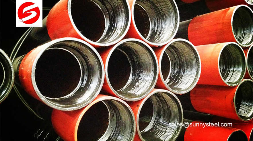
Abrasion resistant pipe bend are widely used at coal-fired power plants for a variety of purposes.

Pipe bend FAQs:
Pipe fittings are necessary to join together pipes, or to change the direction of an existing pipe. Pipes and pipe fittings are made of a variety of materials, depending on the fluid or gas being transported. Most pipe fittings tend to be either threaded or able to slip over the pipes they connect. Whether you are using steel pipes of PVC pipes, a chemical solvent is required to create a seal between the pipe and the fittings.
Measure the required length of the pipe to be installed, keeping in mind the extra length required where the pipe will be inserted into the fitting. Mark this length on the pipe.
How to Calculate a Pipe Bend?
Pipe fittings are necessary to join together pipes, or to change the direction of an existing pipe. Pipes and pipe fittings are made of a variety of materials, depending on the fluid or gas being transported. Most pipe fittings tend to be either threaded or able to slip over the pipes they connect. Whether you are using steel pipes of PVC pipes, a chemical solvent is required to create a seal between the pipe and the fittings.
Measure the required length of the pipe to be installed, keeping in mind the extra length required where the pipe will be inserted into the fitting. Mark this length on the pipe.
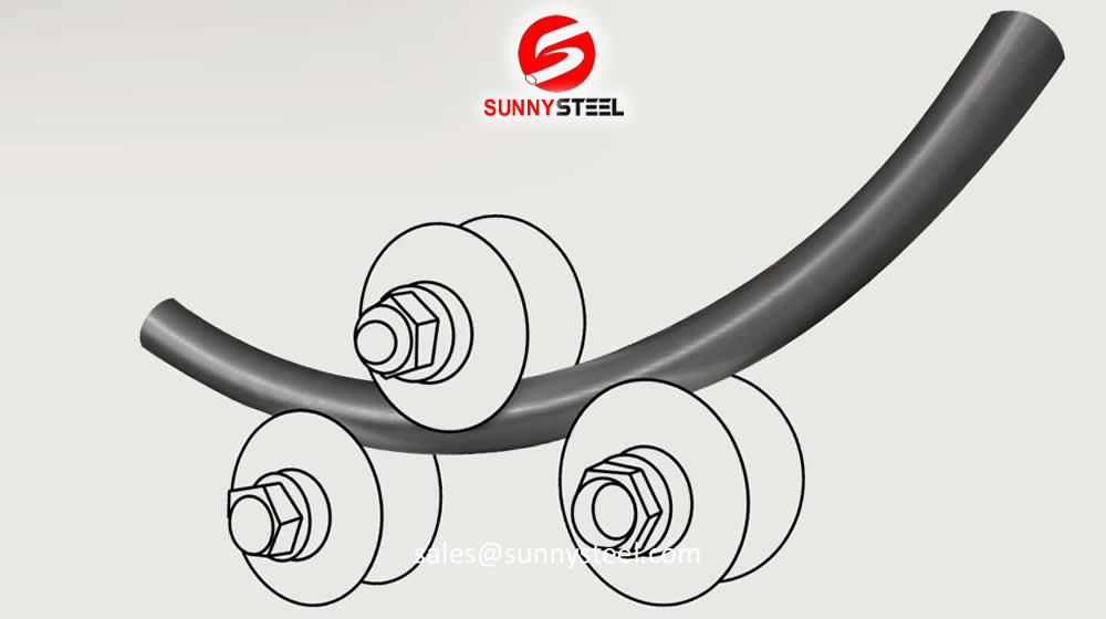
Whether you are bending pipe for running electrical conduit or a metal project, calculating the bend for the start and end point can be an important factor. While there are different types of pipe benders on the market, they all share a common identification for the operation. Identified on all pipe benders is the size of pipe the unit will bend along with a number called the “take up.” The take up measurement is used for adding or deducting an allowance in the overall length of the bend. By following a basic process, you can calculate pipe bends regardless of the type of bender or the diameter of pipe.
Identify the take up measurement that is located on the pipe-bending shoe itself. This is the addition or deduction of measurement to the length of pipe from the front mark on the bending shoe. Also be aware that there is a second center-of-bend mark located approximately in the center of the bending shoe. Also located along the running length of the shoe are angle markings with lines. These numbers and lines correspond to actual angles that can be bent into the pipe by aligning the pipe with the angled line marked on the outside of the shoe.
Bend a 90-degree angle on a ½-diameter pipe with a ½-inch bender. The process will remain the same for different sized pipes and benders, but only the take up measurement will be different. Identified on the shoe for the ½-inch pipe may be the wording “stub take up 5 inches from arrow or line.” The 5 inches is the amount you will deduct from the overall length of the 90-degree bend measurement.
Use the measuring tape and pencil and place a mark at 12 inches from the end of the pipe. This will be the distance from the bend to the end of the pipe. By using the deduction measurement on the shoe, measure back 5 inches from the 12-inch mark and make a solid pencil line.
Lay the pipe on a level surface and insert the pipe into the bender. The solid pencil mark should be placed 5 inches back from the 12-inch mark and should be aligned with the front mark or arrow on the bending shoe. Pull back on the handle in a smooth motion until the pipe sits at a 90-degree position to the level surface. Place the small level against the upright portion of the pipe and check for level. This will give you a perfect 90-degree bend. Check the height of the overall bend by placing the end of the tape measure on the level base and measure the end of the pipe. It should read 12 inches exactly.
Practice with other angled bends by using the deduction measurement and the center of the bend mark on the shoe. All pipe benders may have their own quirks and slight measurement adjustments that will have to be done. The actual end result also depends on how well and secure you hold the pipe in the bender, prior to the first bend you place on the pipe.
Bevelled Ends
The ends of all buttweld fittings are bevelled, exceeding wall thickness 4 mm for austenitic stainless steel, or 5 mm for ferritic stainless steel. The shape of the bevel depending upon the actual wall thickness. This bevelled ends are needed to be able to make a "Butt weld".
Welding Bevel acc.to ASME / ANSI B16.9 and ASME / ANSI B16.28
ASME B16.25 covers the preparation of buttwelding ends of piping components to be joined into a piping system by welding. It includes requirements for welding bevels, for external and internal shaping of heavy-wall components, and for preparation of internal ends (including dimensions and dimensional tolerances).
Our in-hourse R&D team developed bevel ends equipment are good using in thickness 2mm to 20mm pipe fittings, guarantee high efficiency and high quality.
These weld edge preparation requirements are also incorporated into the ASME standards (e.g., B16.9, B16.5, B16.34).


Comments