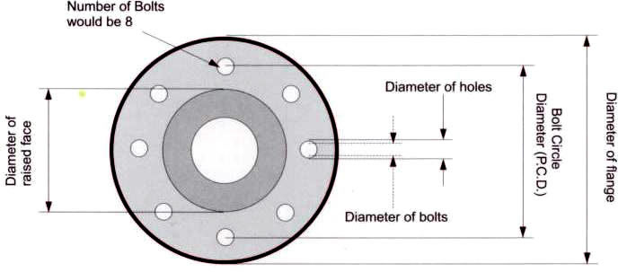
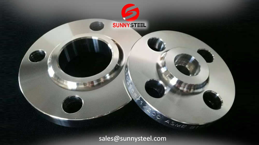
Pipe flanges are basically plates or rings used to connect pipes, valves and other piping equipment to form a piping system.


Welding Neck Flanges
Weld-Neck flanges or welding-neck flanges can be differentiated from all other types of flange by their long tapered hub.
Slip-On Flanges
Slip-On flanges are welded both inside and out to provide sufficient strength and prevent leakage.
Lap Joint Flange
A lap-joint flange is a two-component assembly, with a stub end that has a lap-joint ring flange placed over it.

Threaded Flanges
Threaded flanges are threaded in the bore which match an external thread on the pipe.
General flange standards
All flanges are manufactured in accordance with industry-accepted standards.
| Standard | Specification |
| ASTM A105 | Standard Specification for Carbon Steel Forgings for Piping Applications |
| ASTM A350 | Standard Specification for Carbon and Low-Alloy Steel Forgings, Requiring Notch Toughness Testing for Piping Components |
| ASTM A182 | Standard Specification for Forged or Rolled Alloy and Stainless Steel Pipe Flanges, Forged Fittings, and Valves and Parts for High-Temperature Service |
| ASTM A404 | Specification for Forged or Rolled Alloy Steel Pip Flanges, Forged Fittings, and Valves and Parts Specially Heat Treated for High-Temperature Service (Withdrawn 1974) |
| ASTM A234 | Standard Specification for Piping Fittings of Wrought Carbon Steel and Alloy Steel for Moderate and High Temperature Service |
| ASTM A420 | Standard Specification for Piping Fittings of Wrought Carbon Steel and Alloy Steel for Low-Temperature Service |
| ASTM A403 | Standard Specification for Wrought Austenitic Stainless Steel Piping Fittings |
| ASTM A694 | Standard Specification for Carbon and Alloy Steel Forgings for Pipe Flanges, Fittings, Valves, and Parts for High-Pressure Transmission Service |


Specialty flange
A Specialty flange is a component with a flanged joint that has the same bolting structure as a standard flange, but a specialty flange has its own characteristics.


Flange size & tolerance
Our company offers a wide range of flanges like PL, SW, BL, WN,SO,LJ, ASME/ANSI B16.5 etc., which is precisely engineered in
These Flanges are most durable and manufactures to fit in different size of Pipes.


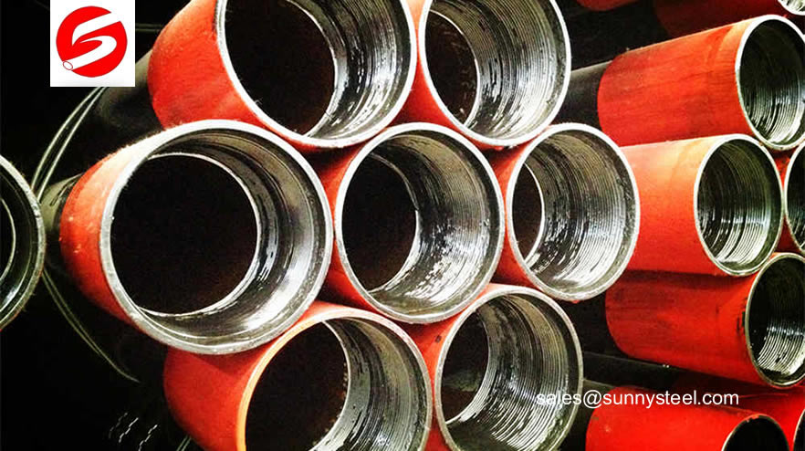
Pipeline & fittings with flanges
Pipe Flange helps to connect piping components in a piping system with the use of bolted connections and gaskets.
- Backpack wear-resistant ceramic lined elbow
- Wear-resistant Alloy Composite Pipe Tee
- Rare Earth Wear Resistant alloy Elbow with flange
- Bimetal Clad Pipe with flange
- Rare earth alloy wear-resistant casting flange pipes
- Ceramic Tile lined elbow
- Ceramic Lined Reducer Pipe with flange

Flange gasket
A flange gasket is a type of gasket made to fit between two sections of pipe that are flared to provide higher surface area.

Steel pipe flange gaskets are used to create seal between two flange faces. The flange face acts at the seal seat and the flange gasket compresses between two flanges, with the bolt compression, to fill all irregularities in the flange face and create a seal. The gasket is selected based on the operating condition such as pressure, temperature and chemical exposure.

Gaskets are available in following three types:
- Full Face Gasket: covers the full face of the flange. Generally used on flat face flanges
- Flat ring Gasket: covers only the sealing surface or the raised face of the flange.
- Metallic Ring Gakset: designed to be fitted in RTJ Flanges.
AWWA Standard flange
AWWA Flange Standards differ from ANSI (American National Standards Institute) and ASME (American Society of Mechanical Engineers) certifications in a variety of ways, the most important being their specificity: AWWA standards evaluate properties that particularly affect potable water use, as opposed to broader industrial flange applications

AWWA Flange Charts and Drawings
These tolerances are a part of ANSI B16.5 and AWWA C207-01 Sec. 4.2 except where noted otherwise.
- AWWA Class B-Ring and Blind Flanges
- AWWA Class B-Hub and Blind Flanges
- AWWA Class D-Ring and Blind Flanges
- AWWA Class D-Hub and Blind Flanges
- AWWA Class E-Ring and Blind Flanges
- AWWA Class E-Hub and Blind Flanges
- AWWA Class F-Ring and Blind Flanges
General Information
American Water Works Association (AWWA) is an international non-profit, scientific and educational association founded to improve water quality and supply. Established in 1881, it has a membership (as of 2012) of around 50,000 members worldwide.
- Full Face Gasket: covers the full face of the flange. Generally used on flat face flanges
- Flat ring Gasket: covers only the sealing surface or the raised face of the flange.
- Metallic Ring Gakset: designed to be fitted in RTJ Flanges.
Listed below are the Dimensional Tolerances to which flanges are manufactured. The limits given are maximum.
| Ring type Slip-on and Blind flanges | HUB type slip-on | ||||
| O.D. | <=24" | +/- 0.6"(1.6mm) | O.D. | <=24" | +/- 0.6"(1.6mm) |
| >24" | +/- .12"(3.2mm) | >24" | +/- .12"(3.2mm) | ||
| I.D. | Socket-Welding | 10" and Samller +.03"(0.8mm),-0" | I.D. | 10" and Samller | +.03"(0.8mm) |
| Slip-on and Lap Joint | 12" and Larger +.06"(1.6mm),-0" | 12"-18" | +/-.06"(1.6mm) | ||
| 20"-42" | +.12"(3.2mm) +.06"(1.6mm) | ||||
| O.D. of Hub | <=12" | +.09"(2.4mm), -.06"(1.6mm) | Diameter of Contact Face | 0.06" Raised Face | +/-.03"(0.8mm) |
| 14"-42" | +/-.12"(3.2mm) | ||||
| Diameter of Contact face | 0.06" Raised Face | +/- .03"(0.8mm) | Diameter of Hub at base | X<=24" | +/-.06"(1.6mm) |
| X>24" | +/-.12"(3.2mm) | ||||
| Deameter of Contact face | <=10" | +.03"(0.8mm), -0" | Diameter of Hub at point of Welding | <=5" | +.09"(2.4mm), -.03"(0.8mm) |
| 12"-42" | +.06"(1.6mm), -0" | >=6" | +.16"(4.0mm), -.03"(0.8mm) | ||
| Drilling | Bolt Circle | 1/2"-24" /26"-42" | Drilling | Bolt Circle | 1/2"-24" /26"-42" |
| +/-.06"(1.6mm) +/-.06" | +/-.06"(1.6mm) +/-.06" | ||||
| Bolt hole spacing | +/-.03"(0.8mm) | Bolt hole spacing | +/-.03"(0.8mm) | ||
| Eccentricity of Bolt circle with respect to bore | .03" Max. (0.8mm) | Eccentricity of Bolt circle with respect to bore | .03" Max. (0.8mm) | ||
| Thickness | 18"& Small | +.12"(3.2mm),-0" | Thickness | 18"& Small | +.12"(3.2mm),-0" |
| 20"-42" | +.19"(1.6mm) | 20"-42" | +.19"(1.6mm) | ||
| Length Thru Hub | <=10" | +/-.06"(1.6mm) | Length Thru Hub | <=10" | +/-.06"(1.6mm) |
| 12"-42" | +/1.12"(3.2mm) | 12"-42" | +/1.12"(3.2mm) | ||
Rigid inspection procedure assures the maintenance of high standards of accuracy in regular day to day production.

AWWA Vs. ANSI Flange Standards

Both the AWWA and ANSI have thorough standards for flanges, and the two standards are different in several ways. AWWA standards provide flange properties intended for potable water use only. In contrast, ANSI standards are aimed at industrial flange applications.
Both the AWWA and ANSI have thorough standards for flanges, and the two standards are different in several ways. AWWA standards provide flange properties intended for potable water use only. In contrast, ANSI standards are aimed at industrial flange applications.
For example, AWWA flange ratings are applicable only at atmospheric temperature, while ANSI ratings cover flange installations from -20°F to 1500°F. AWWA standards provide flange properties intended for potable water use only. In contrast, ANSI standards are aimed at industrial flange applications. For example, AWWA flange ratings are applicable only at atmospheric temperature, while ANSI ratings cover flange installations from -20°F to 1500°F.
ANSI covers numbered class flanges from 150 to 2500, and AWWA standards encompass lettered flange classes B, E, F, and the commonly used class D connection. AWWA provides ratings for a much broader range of nominal pipe sizes (3″-144″) than ANSI provides (1/2″-24″).
Finally, ANSI and AWWA flange standards differ in the breadth of applications discussed. ANSI includes information for welded auxiliary connections and tapping, while AWWA does not address those installations. Also, the AWWA standard only encompasses ring, hub type, blind flanges, and threaded iron flanges while the ANSI standard inlcudes all flange types.
This discussion on AWWA flange standards and ANSI flange standards is based on information from ANSI/AWWA C115/A21.15-99: “American National Standard for Flanged Ductile-Iron Pipe with Ductile-Iron or Gray-Iron Threaded Flanges”, ANSI/AWWA C207-94: “AWWA Standard for Steel Pipe Flanges for Waterworks Service-Sizes 4 In. Through 144 In.”, and ANSI B16.5-1981: “Pipe Flanges and Flanged Fittings”.
Note:
- Ring flanges available overbored or counterbored per customer specification.
- Bolt holes shall be drilled 1/8th inch larger in diameter than the nominal diameter of the bolt, except for flanges larger than 84 inch in diameter which shall be drilled 3/16th inch larger than the nominal diameter of the bolt.
- Drilling same as ANSI/ASME B16.1 125 lb and B16.5 150 lb pattern.
- Flanges available overdrilled to accommodate insulators.
- AWWA recommends the use of dished head assemblies as alternate to blind flanges, sizes over 72" nominal.
- AWWA C207-01 Class B and D Hub Flanges are identical to Industry Standard Class 125 Light Weight Flanges.
DIN flanges
DIN Flanges production and processing of finished solution treatment must be enclosed , so that product performance is optimal.
Applications Of DIN Flanges
In many applications, engineers need to find a way to close off a chamber or cylinder in a very secure fashion, usually because the substance inside must differ from the substance outside in composition or pressure.
- DIN Flanges used in Chemical and petrochemical processing
- DIN Flanges used in electronics
- DIN Flanges used in processing equipment for maintaining product purity in handling foods, synthetic fibers
- DIN Flanges used in marine and offshore engineering
Characteristics of DIN Flanges
DIN Flanges production and processing of finished solution treatment must be enclosed , so that product performance is optimal.
- DIN Flanges is highly resistant to various reducing chemicals
- DIN Flanges is excellent resistance to caustic alkalies
- DIN Flanges is high electrical conductivity
- DIN Flanges is excellent corrosion resistance to distilled and natural waters
- DIN Flanges is resistance to neutral and alkaline salt solutions
- DIN Flanges is excellent resistance to dry fluorine
- DIN Flanges is widely used to handle caustic soda
- DIN Flanges is good thermal, electrical and magnetostrictive properties
- DIN Flanges is offers some resistance to hydrochloric and sulfuric acids at modest temperatures and concentrations
Dimensions of DIN Flanges
| Flange Nominal Diameter | Pressure Rating (PN) | |||||
|---|---|---|---|---|---|---|
| **Nominal BSP Pipe Size | PN6 | PN10 | PN16 | PN25 | PN40 | |
| DN 10 | 75 | 90 | 90 | 90 | 90 | O.D. |
| 3/8" | 50 | 60 | 60 | 60 | 60 | PCD (bolt circle) |
| 4 x 11 | 4 x 14 | 4 x 14 | 4 x 14 | 4 x 14 | # of holes x diam. of holes | |
| DN 15 | 80 | 95 | 95 | 95 | 95 | O.D. |
| 1/2" | 55 | 65 | 65 | 65 | 65 | PCD (bolt circle) |
| 4 x 11 | 4 x 14 | 4 x 14 | 4 x 14 | 4 x 14 | # of holes x diam. of holes | |
| DN 20 | 90 | 105 | 105 | 105 | 105 | O.D. |
| 3/4" | 65 | 75 | 75 | 75 | 75 | PCD (bolt circle) |
| 4 x 11 | 4 x 14 | 4 x 14 | 4 x 14 | 4 x 14 | # of holes x diam. of holes | |
| DN 25 | 100 | 115 | 115 | 115 | 115 | O.D. |
| 1" | 75 | 85 | 85 | 85 | 85 | PCD (bolt circle) |
| 4 x 11 | 4 x 14 | 4 x 14 | 4 x 14 | 4 x 14 | # of holes x diam. of holes | |
| DN 32 | 120 | 140 | 140 | 140 | 140 | O.D. |
| 1 1/4" | 90 | 100 | 100 | 100 | 100 | PCD (bolt circle) |
| 4 x 14 | 4 x 18 | 4 x 18 | 4 x 18 | 4 x 18 | # of holes x diam. of holes | |
| DN 40 | 130 | 150 | 150 | 150 | 150 | O.D. |
| 1 1/2" | 100 | 110 | 110 | 110 | 110 | PCD (bolt circle) |
| 4 x 14 | 4 x 18 | 4 x 18 | 4 x 18 | 4 x 18 | # of holes x diam. of holes | |
| DN 50 | 140 | 165 | 165 | 165 | 165 | O.D. |
| 2" | 110 | 125 | 125 | 125 | 125 | PCD (bolt circle) |
| 4 x 14 | 4 x 18 | 4 x 18 | 4 x 18 | 4 x 18 | # of holes x diam. of holes | |
| DN 65 | 160 | 185 | 185 | 185 | 185 | O.D. |
| 2 1/2" | 130 | 145 | 145 | 145 | 145 | PCD (bolt circle) |
| 4 x 14 | 4 x 18 | 4 x 18 | 8 x 18 | 8 x 18 | # of holes x diam. of holes | |
| DN 80 | 190 | 200 | 200 | 200 | 200 | O.D. |
| 3" | 150 | 160 | 160 | 160 | 160 | PCD (bolt circle) |
| 4 x 18 | 8 x 18 | 8 x 18 | 8 x 18 | 8 x 18 | # of holes x diam. of holes | |
| DN 100 | 210 | 220 | 220 | 235 | 235 | O.D. |
| 4" | 170 | 180 | 180 | 190 | 190 | PCD (bolt circle) |
| 4 x 18 | 8 x 18 | 8 x 18 | 8 x 22 | 8 x 22 | # of holes x diam. of holes | |
| DN 125 | 240 | 250 | 250 | 270 | 270 | O.D. |
| 5" | 200 | 210 | 210 | 220 | 220 | PCD (bolt circle) |
| 8 x 18 | 8 x 18 | 8 x 18 | 8 x 26 | 8 x 26 | # of holes x diam. of holes | |
| DN 150 | 265 | 285 | 285 | 300 | 300 | O.D. |
| 6" | 225 | 240 | 240 | 250 | 250 | PCD (bolt circle) |
| 8 x 18 | 8 x 22 | 8 x 22 | 8 x 26 | 8 x 26 | # of holes x diam. of holes | |
| DN 175 | 315 | 315 | 330 | 350 | O.D. | |
| 7" | 270 | 270 | 280 | 295 | PCD (bolt circle) | |
| 8 x 22 | 8 x 22 | 12 x 26 | 12 x 30 | # of holes x diam. of holes | ||
| DN 200 | 320 | 340 | 340 | 360 | 375 | O.D. |
| 8" | 280 | 295 | 295 | 310 | 320 | PCD (bolt circle) |
| 8 x 18 | 8 x 22 | 12 x 22 | 12 x 26 | 12 x 30 | # of holes x diam. of holes | |
| DN 250 | 375 | 395 | 405 | 425 | 450 | O.D. |
| 10" | 335 | 350 | 355 | 370 | 385 | PCD (bolt circle) |
| 12 x 18 | 12 x 22 | 12 x 26 | 12 x 30 | 12 x 33 | # of holes x diam. of holes | |
| DN 300 | 440 | 445 | 460 | 485 | 515 | O.D. |
| 12" | 395 | 400 | 410 | 430 | 450 | PCD (bolt circle) |
| 12 x 22 | 12 x 22 | 12 x 26 | 16 x 30 | 16 x 33 | # of holes x diam. of holes | |
| DN 350 | 490 | 505 | 520 | 555 | 580 | O.D. |
| 14" | 445 | 460 | 470 | 490 | 510 | PCD (bolt circle) |
| 12 x 22 | 16 x 22 | 16 x 26 | 16 x 33 | 16 x 36 | # of holes x diam. of holes | |
| DN 400 | 540 | 565 | 580 | 620 | 660 | O.D. |
| 16" | 495 | 515 | 525 | 550 | 585 | PCD (bolt circle) |
| 16 x 22 | 16 x 26 | 16 x 30 | 16 x 36 | 16 x 39 | # of holes x diam. of holes | |
| DN 500 | 645 | 670 | 715 | 730 | 755 | O.D. |
| 20" | 600 | 620 | 650 | 660 | 670 | PCD (bolt circle) |
| 20 x 22 | 20 x 26 | 20 x 33 | 20 x 36 | 20 x 42 | # of holes x diam. of holes | |
| DN 600 | 755 | 780 | 840 | 845 | O.D. | |
| 24" | 705 | 725 | 770 | 770 | PCD (bolt circle) | |
| 20 x 24 | 20 x 27 | 20 x 33 | 20 x 36 | # of holes x diam. of holes | ||
Rigid inspection procedure assures the maintenance of high standards of accuracy in regular day to day production.
DIN Flanges Norms
All the Raw Materials received by our company are subject to chemical and physical test and weighed immediately on receipt only thereafter they are taken in the stock.
The Welding neck flanges is normally referred to as the high hub flange.
Welding Neck Flanges
A weld neck flange (also known as a high-hub flange and tapered hub flange) is a type of flange.
Threaded Flanges
Threaded flanges are widely demanded as pipe flanges i.e called as threaded pipe flanges used in different industrial applications.
Slip-on flange
Slip-On flanges or SO flanges are commonly lower in price than weld-neck flanges, and to this effect are a popular choice for our customers.
Blind Flanges
The blind flange is used to close ends of piping systems. It is a kind of round plate with no center hold but with all the proper bolt holes.
Flange facing types according to DIN EN 1092-1
Flanges and their joints - Circular flanges for pipes, valves, fittings and accessories, PN designated - Part 1: Steel flanges
This European standard specifies requirements for circular steel flanges in PN designations PN 2,5 to PN 400 and nominal sizes from DN 10 to DN 4000. This standard specifies the flange types and their facings, dimensions, tolerances, threading, bolt sizes, flange face surface finish, marking, materials, pressure/ temperature ratings and flange masses.
Flange faces have to be smooth enough to ensure a tight, leak-free seal for bolted flanges.
Type A: flat face
Type B: raised face
Type C: tongue face
Type D: groove face
Type E: spigot
Type F: recess
Type G: O Ring recess
Type H: O Ring groove

ANSI flanges
The American National Standard Institute, ANSI, has been overseeing guidelines and standards for products manufactured through several sectors.

WHAT IS ANSI?
ANSI-approved flanges are used for the industrial market which handles gas, air and steam process systems. Originally formed in 1918, the American National Standards Institute is headquartered in Washington, DC, and is widely recognized as the American organization responsible for overseeing the national standards and conformity assessment system for products, services, processes, systems, and personnel.
ANSI works domestically with American government agencies and organizations, as well as with international entities, to make ANSI standards useful around the world.
Prior to the creation of ANSI, standards for engineering and equipment such as flanges were developed by the American Institute of Electrical Engineers (AIEE or IEEE), the American Society of Mechanical Engineers (ASME), the American Institute of Mining, Metallurgical, and Petroleum Engineers (AIME), the American Society of Civil Engineers (ASCE), and the American Society for Testing and Materials (ASTM International) as members of the United Engineering Society, or UES.
Types of ANSI Flanges
The American National Standards Institute (ANSI) calls for the use of an ANSI flange to be used on specific applications. The ANSI flange is a three-part flange consisting of one flat flange, one flange machined to take a rubber O-ring and the rubber O-ring. The rubber O-ring is placed into the machined groove in one side of the flange and the assembly is tightened against the flat-faced side of the ANSI flange and secured with bolts which are torqued to a specific amount of pressure or tightness. This flange is welded to the ends of pipe to create an easy-to-separate connection. Other variations use a larger flat gasket that fits inside of the bolt circle of the flange.

While not rated for excessive pressure, the ANSI flange is commonly used on pipelines transporting air, water and steam under low to moderate pressure. While some flange types use a gasket that not only covers the flange face, the ANSI flange covers the bolt circle as well. These flange bolts run through the gasket and aid in the aligning of the gasket.
The ANSI flange does not use this type of gasket, thus the gasket must be slipped into position after some of the bottom bolts have been put into place. The bolts aid in supporting the gasket that floats in the center of the flange, sealing only the flange opening and creating a leak-proof passage for the pipeline products to pass through when the flange is tightened.
The lower pressure rating of the ANSI flange allows the gasket to remain floating in the middle of the two flanges instead of being held in place by the flange bolts. Unfortunately, this also creates a seal that, while sufficient for its intended purpose, is prone to leaking or blowing out completely much easier than the larger gaskets that are trapped in place by the flange bolts. The smaller gaskets also require more skill to install as they are not a simple drop-into-position type of gasket.
The majority of problems with an ANSI flange originate at the time of assembly. Some installers use a screwdriver to push the gasket into position while tightening the flange bolts. This can create a small nick that ultimately develops into a crack over time. Other problems that contribute to defects in sealing are getting grease on the gasket, trapping debris between the flanges and improperly lining up gaskets at the time of installation.
Price and mechanical properties are higher than ordinary casting flange a grade. The flange is a part that connects the pipe with the pipe and the valve, is connected to the pipe end. It is also used for the flange on the equipment inlet and outlet.

Purpose
Flanges are used to attach a series of pipes or other flanges together. Some flanges, such as in the oil and gas sector, are required to sustain under high amounts of pressure. ASNI provides standards to flange manufactures to test flanges before they can be marketed to a particular sector.
Significance
ANSI provides standards on flanges depending upon pressure in pounds per second per inch (PSI), according to size in inches of the flange. Pressure and size are dependent upon whether the flange is welded to the pipe, threaded or bolted.
Considerations
Depending on the material the flange is made from, such as cast iron or steel, and the type of threaded material used for fittings, every flange is designated to a particular class. From these class ratings, several requirements, such as pressure-temperature rating, bolt and nut dimensions, coating material and several other factors, make up the standards according to the flange characteristics.
Standards of ANSI Flanges:
The classes for flat face flanges are Class 125 and Class 250. The classes for ring joint flanges, tongue and groove flanges and raised flanges are: Class 150, Class 300 (Class 400 - rarely), Class 600, Class 900, Class 1500 and Class 2500. ANSI flanges are divided into classes, depending on pressure, temperature and the type of material used.
Welding Neck Flanges
- ASME/ANSI B16.5 Class 150 WN
- ASME/ANSI B16.5 Class 300 WN
- ASME/ANSI B16.5 Class 600 WN
- ASME/ANSI B16.5 Class 900 WN
- ASME/ANSI B16.5 Class 1500 WN
- ASME/ANSI B16.5 Class 2500 WN
- ASME B16.47 Series A/MSS SP-44 Class 150 WN
- ASME B16.47 Series A/MSS SP-44 Class 300 WN
- ASME B16.47 Series A/MSS SP-44 Class 600 WN
- ASME B16.47 Series A/MSS SP-44 Class 900 WN
RTJ Flanges, Ring Type Joint Flange
- Dimensions of Ring Joint Facings
- Ring Joint Facings ASME/ANSI B16.5 & B16.47-1
- Ring Joint Facings ASME/ANSI B16.5 & B16.47-2
- Ring Joint Facings ASME/ANSI B16.5 & B16.47-3
- Ring Joint Facings ASME/ANSI B16.5 & B16.47-4
Threaded Flanges, TH Flanges
Slip-on flange
- ASME/ANSI B16.5 Class 150 SO
- ASME/ANSI B16.5 Class 300 SO
- ASME/ANSI B16.5 Class 600 SO
- ASME/ANSI B16.5 Class 900 SO
Lap Joint Flanges
- ASME/ANSI B16.5 Class 150 LJ
- ASME/ANSI B16.5 Class 300 LJ
- ASME/ANSI B16.5 Class 600 LJ
- ASME/ANSI B16.5 Class 900 LJ
- ASME/ANSI B16.5 Class 1500 LJ
- ASME/ANSI B16.5 Class 2500 LJ
Blind Flanges, BL Flange, BLRF